Successful Flex Circuit Design Guidelines
With the use of sensors and technology in everything from mobile phones to refrigerators to automobiles to wearable medical devices, circuit boards are a component in many different types of products. In today’s world of electronics, any product with an on/off switch contains a circuit board. Due to their versatility, the use of flex circuits is one of the fastest growing product market segments.
With the introduction of flex and rigid-flex circuits, engineers have been given the opportunity to be more creative in designing new and innovative products. Flex and rigid-flex boards are built to fit into tight, three-dimensional spaces while ensuring resistance to mechanical wear and vibration. Engineers can design products that require boards to fit into tight spaces, twist and turn for packaging, and make the product live in a more dynamic environment. These flexible circuits have the same performance levels as traditional rigid-FR4 boards however, they have their own nuances and considerations when it comes to design, fabrication and assembly.
Design/Layout
When designing a flex circuit, it is important to know the specific application for the board. Will it be used in a static or dynamic environment? If the board is to reside in a static environment, with little to no movement, the circuit design needs to have the appropriate amount of flexibility so that it can be easily installed within the product. Alternatively, if the board is to exist in a dynamic environment, where the board will continuously flex back and forth, a level of flexibility that can withstand continuous movement needs to be considered in the design.
Will the application require a flex board or a rigid-flex board? If the product requires one-sided surface mount technology, then an all flex board is the best option. If the product requires two-sided surface mount technology, then a rigid-flex board is needed.
Whether it is a hardware engineer, mechanical engineer, or an experienced Layout board designer, everyone is a bit apprehensive their first time laying out a flex circuit. Their assumption is the approach to designing a flex circuit is very different than a rigid board. But the fact of the matter is that laying out a flex circuit is very similar to a rigid board with just a few differences. You set up all your layers in the software just a like a rigid board. The output files are all the same. The only real differences are cover layer, stiffener layer, and some basic design rules to keep in mind. Understanding that a flex circuit will be flexing in nature means you need to make sure you keep key features such as vias, terminating traces, and sharp angles away from the bending regions. Flex circuit is made of polyimide material so it is more difficult to process so keep your traces, vias, annular rings, pads, and spacing as big as possible. I often get asked how small of a trace or via that can be used. You can go as small as you like but it will be more difficult to manufacture and reliability comes in play. You can get away with a lot more tight features on a rigid board than you can on a flex circuit. Typically on a rigid board, solder mask is applied on the outer layers to protect the copper features. On a flex board, the outer copper features are usually protected by a cover layer. In the design file, the layout designer should create this cover layer the same as a solder mask layer. The last difference with a flex design is stiffener. Stiffeners are used to add support to certain regions of a flex circuit board. The stiffeners can be in multiple regions of a flex circuit and they can be on either side of the board. In the design file, if all the stiffeners are represented in one file then they need to be identify in the fabrication drawing which side of the board they need to be apply. Otherwise, a separate layer should be created for the top and bottom stiffeners of the flex circuit.
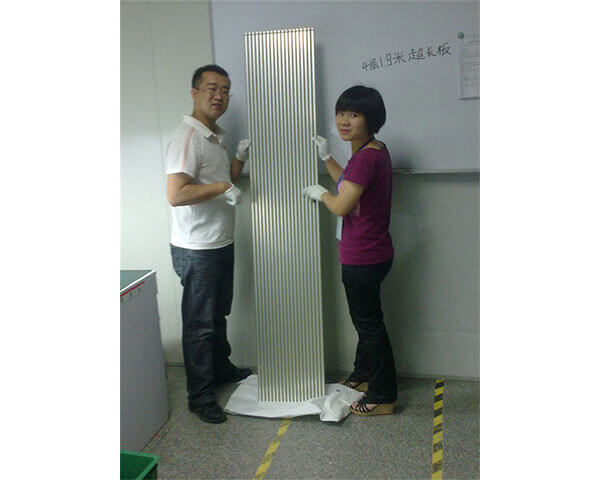
When additional support for a specific area on the flex circuit board is required or protection is needed for attached components or connectors, the best option is to include a stiffener in the design. This will eliminate the circuit from moving and protect the integrity of the solder joints. It is important to remember that the stiffener is best placed on the opposite side of the component it is supporting. There are numerous types of stiffeners to choose from; polyimide, FR4, stainless steel, aluminum or many other options. The thickness of the stiffener is dependent upon how the board will be used. The thicker the stiffener, the more support it provides. If the board is being used in small/tight spaces the thickness of the stiffener may be an issue that requires a thinner stiffener. SEE STIFFENER PICTURE.
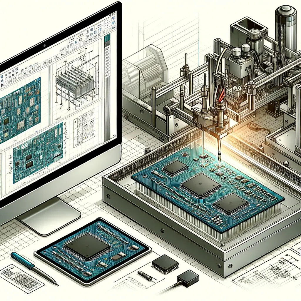
Now that the designer has completed his/her first flex circuit, he is task to layout his first rigid-flex. The level of confusion and apprehension just went up five fold. Engineers often think that the flex portion of the board is glued or somehow attached to the rigid section of the board. SEE RIGID-FLEX PICTURE. Rigid-flex is built just like all rigid and flex boards with the method of layers stacked on top of layers. When it comes to designing rigid-flex, the approach is the same way as the other circuit boards. The main difference is that the certain regions of the rigid layers will be blank in the design file. The board manufacturer will recognize this as a flex region and will plan the board accordingly.
Unlike a rigid board, flex circuit has a lot of varies so having a detail fabrication drawing to accompany the design is very important. The fabrication drawing should call out all the details so it is not overlook by the manufacturer. The worst thing is to have the manufacturer assumed what you require. Flex circuits has many moving variables so the details are very important.
Material
Flex circuit is generally built with polyimide material. Most manufacturers in the USA will use polyimide made by Dupont. Manufacturers outside of the USA might use other material suppliers due to cost and availability. However, because flex circuit is unique it is a good idea to use the same material in prototype that will eventually be used in volume production. During testing, you are trying to see how many cycles the flex circuit can withstand. Below is a general rule on a flex circuit bend radius. Exhibit A.
The bend radius rule is just a general guideline. The absolute way to determine how much a flex circuit can bend or how many cycles it will withstand is to stress test it.
A couple of factors will affect how much a flex circuit can flex. Material selection is very important. Although the thickness of the board will determine the flexibility, material will help the quality and life cycle of the flex circuit. The type of copper used on a flex circuit is very critical. There are two types of copper available in the market, ED Copper (Deposited Copper) and Roll Annealed Copper. If possible, ED copper should be avoided because it is a plated process and the copper will be very brittle. Roll Annealed copper is preferred. The copper is rolled onto the flex material, therefore, it is very malleable. With this said, it is also important to call out the grain direction on your fabrication drawing. You want the grain to go in the same direction as your bend direction. Solid copper areas such as ground planes should be crossed-hatch when possible. This will help make the flex circuit more flexible.
Fabrication
Now that the design is completed, lets get the flex board built as fast as possible. Like all engineering projects, this flex board is behind schedule so we need it by tomorrow. After all, rigid boards can be built in one or two days so why not flex circuits. Stop! Not so fast, my friend.
When fabricating a flex circuit requires longer lead time. Flex boards are more difficult to manufacture than traditional rigid circuit board therefore requiring more manufacturing time. Flex circuits built with polyimide material. The material is thin, fragile and difficult to handle. The drilling of the vias is different. The chemistry to plate the vias is different. There might be a lot of hand labor involved with the stiffener(s) and coverlay. All these differences restrict most manufacturer from building flex circuits faster than three working days. Here, we are just talking about a 2 layer flex circuits. If the flex circuit has higher layer count, the turn time can go upward to two to three weeks to manufacture.
Now we go into manufacturing of rigid-flex circuits. Rigid-flex circuit is truly an entirely different animal. The upfront planning and camming of a Rigid-flex can easily take 2-3 days to perform before the board can actually be release to the manufacturing floor. This upfront engineering work is very critical because rigid-flex takes many different steps and every step is critical to the successful manufacture of the rigid-flex. One of the most important thing to note is rigid-flex comes in many different stack-up. It is rare to see multiple rigid-flex jobs on a manufacturing floor with similar stack-up. With a rigid board, all 6 layer boards are processed the same way. With rigid-flex, you can have 5 jobs with 6 layer on the manufacturing floor and they can all be process differently.
Example-
Board #1 -– 6 layer board—have 4 layer rigid with 2 layer flex.
Board #2 –-6 layer board— have 3 layer rigid with 3 layer flex.
Board #3 —6 layer board—4 layer rigid with 2 layer flex but the 2 flex layers are on different layers.
The other difficulty of rigid-flex circuit manufacturing is the combination of working with two different type of material. Rigid-flex is combining rigid material with flex circuit material. They have two different properties so it is tricky to work with. This is the reason why you do not see too many circuit board manufacturers build rigid and flex circuits in the same facility. Each circuit board manufacturer sticks to what they build best, respectively. The most common failure with rigid-flex circuit is attribute to the plating process. If the plating of the vias is not done properly, it will lead to voids, cracking, and delamination. The two different materials have different Z-axis expansion rate so improper plating will exposed the bad quality easily.
Due to the complexity of a flex circuit, the material cost, processing time, chemistry, drilling and handling, the cost to fabricate a flex board is higher than that of a traditional rigid circuit board. Purchasers sometime are shock at the price different between rigid and flex circuits. Hopefully, they now understand why there is a price difference and why flex circuits cannot be built as fast as traditional rigid circuit boards.
As electronic products become smaller, flex circuit will become more popular and common in the electronic industry. Although the cost is higher, there are many useful applications for flex circuits. Flex circuits can be fold up and cramp into a tight space. Flex circuits can move back and forth in a dynamic environment. The electronic industry does not have to be so rigid anymore. Flex circuit can help designers expand their imaginations and develop cooler and more advanced electronic products.
Article by Tuan Tran, Director at hitechcircuits