PCBA Testing and Quality Assurance
PCB Assembly Testing and Inspection
PCBA testing refers to the test of electrical conductivity and input-output value based on PCBA board with electronic components.
Why PCBA testing?
In the design of PCB, there is a numerical relationship between different test points, such as voltage and current. However, the process flow of PCBA production and processing is very complex, including many important processes such as the PCB manufacturing process, component procurement, and inspection, SMT patch assembly, dip plug-in PCBA test. In the process of production and processing, various problems may occur due to improper equipment or operation. Therefore, it is necessary to use professional test equipment or a manual multimeter to test the test points, To verify whether the actual PCBA Board meets the design requirements and ensure that each product will not have quality problems.
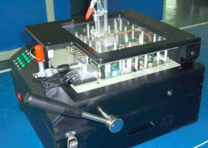
PCBA testing is a key step to ensure the quality of production and delivery. FCT test fixture is made according to the test point program and test steps designed by customers, and then the PCBA board is placed on the FCT test rack to complete the test.
Testing is crucial to ensure high quality products are delivered to customers. Thankfully board assemblers offer multiple layers of testing and inspection to ensure high-quality, assembled Circuit boards are produced and delivered to customers. Despite all efforts to prevent errors, printed circuit board assembly is a complex process and defects sometimes occur relating to a variety of issues from incorrect component loading to failures in SMT equipment. Thorough testing and inspection occurs throughout the production process to ensure problems are captured early on, ensuring high quality and yield.
Visual Inspection of Solder Paste
Visual inspection is a vital element in ensuring problems are captured and corrected as early in the process as possible, reducing the time and cost associated with rework and wastage. Visual inspection begins with the solder application. Inspection at this stage checks for correct deposition of solder paste on pads to ensure components reflow properly. Here testing helps prevent solder bridges, open circuits or fragile joints prone to failure.
Pre and Post Reflow Inspection
Pre and post reflow inspection are important elements in quality control. Pre-reflow inspection catches placement errors at a point where they are easy to repair, avoiding repetitive mistakes early in the process. This is important with products like automotive boards where regulatory compliance require that boards cannot be reworked. Components and boards are heat sensitive and detection of errors at this stage can avoid their damage or destruction. Post-reflow inspection can be manual or with AOI.
A ‘first article’ inspection is performed on a run to ensure all SMT feeders are set up correctly and that there are no issues like worn vacuum nozzles or alignment of the vision system. Board assemblers can offer a special ‘First Article Service’ that enables a rapid and cost effective pre-production process by expediting a production of a few boards to designers for testing prior to a full run.
Post reflow BGA inspection and testing, along with other leadless parts require special considerations as the component package shadows solder joints making inspection impractical without special equipment. Inspection can be conducted by a range of devices including: computed-tomography (CT) scanning, specially angled optics microscopes, endoscopes and X-ray machines.
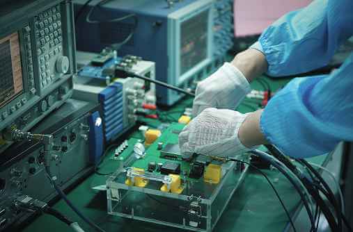
Flying Probe Testing
Flying probe testing is good for where a PCB test jig is prohibitively expensive. Flying probe has relatively low setup cost and a test procedure can be designed and implemented in a single day. Assembled PCBs with all components placed are compared electrically against the measurements from a golden board for verification. It can conduct open, short, orientation and component value circuit checks. This can help verify correct component placement and alignment.
For PCB assembly, in order to ensure high quality, we do and provide related testing and inspection, include:
IQC: Incoming Materials Inspection
First Article Inspection for every process
IPQC: In Process Quality Control
QC: 100% Test & Inspection
QA: QA based on sample inspection plan
Workmanship: IPC-A-610
Quality Management based on ISO9001:2008, ISO13485:2003, ISO/TS16949:2016 and ISO14001:2004
Automatic Optical Inspection (AOI)
Hi-pot test
In-circuit Test (ICT)
Vibration test
Functional test (FCT)
Burn in test
Reliability test
Thermal cycle test
How to test the PCBA board?
1. PCBA board manual test
Manual testing is to test directly by the vision and confirm the component mounting on PCB through vision and comparison. This technology is widely used. However, the large number and small components make this method more and more unsuitable. Moreover, some functional defects are not easy to be found, and the data is not easy to collect. In this way, more professional testing methods are needed.
2. PCBA board automatic optical inspection (AOI)
Automatic optical testing, also known as automatic visual testing, is carried out by a special tester. It is used before and after reflow and has a good effect on the polarity inspection of components. Easy-to-follow diagnosis is a common method, but this method is poor in short circuit identification.
3. PCBA board flying needle tester
Needle testing has been widely welcomed in the past few years due to advances in mechanical accuracy, speed, and reliability. In addition, the requirements for the test system with fast conversion and fixture-free capability required for prototype manufacturing and low-yield manufacturing make the flying needle test the best choice.
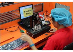
4. PCB Assembly board function test
This is the test method of a specific PCB or a specific unit, which is completed by special equipment. Functional tests mainly include final product tests and hot mock-up.
5. PCB Assembly manufacturing defect analyzer (MDA)
The main advantages of this test method are low initial cost, high output, easy-to-follow diagnosis, fast and complete short circuit, and open-circuit test. The disadvantage is that the function test cannot be carried out, there is usually no test coverage indication, the fixture must be used, and the test cost is high.
What is the testing principle of PCB Assembly by fixture?
PCB Assembly testing is a key step to ensure the quality of production and delivery. It refers to making FCT test fixtures according to the test points, procedures and test steps designed by customers, and then placing the PCBA board on the FCT test fixture to complete the test process. The test principle of PCBA is that: connect the test points on the PCBA board through the FCT test fixture(frame) to form a complete path, then connect the computer and the program tool (programmer), and upload the MCU program. The MCU program will capture the user’s input action (such as long pressing the switch for 3 seconds), and control the on-off of the adjacent circuit (such as LED flashing) or drive the motor to rotate through calculation. By observing the voltage and current values between the test points on the FCT test fixture, and verifying whether these input and output actions are consistent with the design, and so, the test of the entire PCBA board would called completed.
Want to know more? Contact me at [email protected]