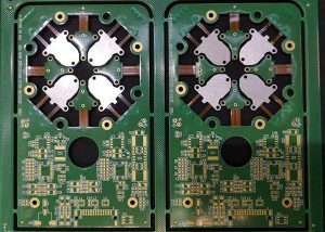
Rigid flex pcb board
Hitech Circuits Co., Ltd is a professional rigid flex pcb printed circuit board manufacturer & supplier from China, our rigid-flex pcb board saves production time, minimize product size and improve equipment reliability, suitable for mobile phones, digital cameras, medical devices, smart control system, and other smart smart devices. If you are looking for long term rigid flex pcb and other pcb products partner in China, Hitech is the right company you are looking for, don’t hesitate to contact [email protected] if you need any help from us.
What is rigid flex pcb board?
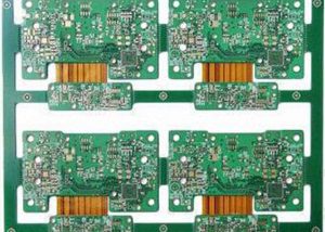
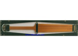
Rigid-flex PCB board, it is a circuit board that combines flexible and rigid circuit board technology in the application. Most rigid-flex boards are composed of multiple layers of flexible circuit boards, which are attached to one or more rigid boards from the outside and/or from the inside, depending on the design of the application. The flexible substrate is designed to be in a constant deflection state, and is usually formed as a deflection curve during rigid flex pcb manufacturing or assembly.
Hitech rigid flex pcb manufacturing process
After the production of FPC flexible boards is completed, the production of Hitech rigid flex pcb boards can be completed through the following processes.
1. Punching
Drill holes on FR4 and PP film, and the design on the alignment hole is not the same as the general through hole. After the punching is completed, browning is required.
2. Riveting
Laminate copper clad laminates, PP adhesives, and FPC circuit boards and place them neatly. The original old process is to laminate and pressing step by step, but it is a waste of time. After many attempts, we found that the stacking process can be completed once.
3. Laminate
This is a relatively complete step in the production of rigid-flex pcb board. Most of the materials are integrated for the first time. First, the bottom layer is copper clad laminate and PP film, above are the FPC flexible board produced in the previous process, and a PP film is placed on the FPC flexible board, then place the last layer of copper clad laminate. All materials to be laminated are placed in order and pressed together.
4. Trimming
That is to remove the part of the circuit board where there is no circuit at the edge of the circuit board currently and in the future. Afterwards, it is necessary to measure whether the material has excessive expansion and contraction. Because the PI used in the production of flexible boards is also expansion and contraction, this has a very large impact on the production of circuit boards.
5. Drilling
This step is the first step to turn on the entire circuit board, and the production parameters should be produced according to the design parameters.
6. Desmear
First, remove the scum generated by the drilling of the circuit board, and then use plasma cleaning to clean the through holes and the board surface.
7. Immersion copper
This step is the process of electroplating through holes, also known as hole metallization. Realize through-hole power conduction.
8. Plate plating
Partially electroplating copper on the upper surface of the electroplating hole makes the copper thickness above the through hole exceed a certain height of the copper clad board surface.
9. Outer dry film positive film production
The same as the production process of the anti-corrosion dry film of the FPC board, the circuit to be etched on the copper clad board is made. After the development is completed, check the circuit.
10. Graphic plating
After the initial copper sinking, pattern electroplating is performed, and the current time and copper plating wire are used according to the design requirements to reach a certain electroplating area.
11. Alkaline etching
12. Print solder mask
This step has the same effect as the FPC board protective film. We see that the PCB rigid board is generally green. This step is generally called green oil printing. After the printing is completed, the inspection is carried out.
13. Open the cover
Cover opening, which is the area where the FPC board is located, but the area not needed by the rigid board is laser cut to expose the FPC board.
14. Curing
It is also a baking process.
15. Surface treatment
Generally, at this time, a rigid-flex PCB board has been manufactured, and only the metallization treatment is required on the surface of the circuit board, which can play a role in preventing wear and oxidation. Generally, this process is to soak the circuit board in a chemical solution, and the metal elements in the solution are densely distributed on the circuit board circuit.
16. Characters printing
The positions of the parts to be assembled and some basic product information are printed on the rigid-flex board in the form of characters.
17. Test
This is a process of checking whether the circuit board is qualified. The test items are tested for electrical properties according to customer requirements. The tests generally include impedance test, open and short circuit test and so on.
18. Final inspection
19. Packaging and shipping
There are many ways to package circuit boards. Generally, Hitech use packaging bags to separate them, and then use a vacuum packaging machine to vacuum package the rigid-flex PCB boards .
The advantages of rigid-flex PCB board
1). It can effectively save the space on the circuit board and eliminate the use of connectors
Because the FPCB and rigid pcb board has been combined, the space that originally needed to use the connector can be saved. For some circuit boards with high-density requirements, less connectors will be better. In this way, it also saves the cost of parts using the connectors. In addition, the space between the two boards can be made tighter by eliminating the need for connectors.
2). The signal transmission distance is shortened and the speed is increased, which can effectively improve the reliability
The traditional signal transmission through the connector is “circuit board→connector→flexible pcb board→connector→circuit board”, while the signal transmission of the rigid-flex PCB board is reduced to “rigid circuit board→flexible pcb board→rigid circuit board”, signal transmission distance between different media is shortened, and the problem of signal transmission attenuation between different media is also reduced. Generally, the circuit on the PCB board is made of copper, while the contact terminal of the connector is gold-plated, and the solder pin is fully tin-plated. Moreover, solder paste is required to be soldered on the circuit board, and the signal transmission between different media will inevitably be attenuated. If you switch to a rigid-flex PCB board, these media will become less, and the signal transmission ability can be relatively improved. For some products that require higher signal accuracy, it helps to improve their reliability.
3). Simplify product assembly and save assembly time
The use of a rigid-flex PCB board can reduce the man-hours for SMT parts, because the number of connectors is reduced. It also reduces the man-hours for assembly of the whole equipment, because it eliminates the assembly action of inserting the FPC board into the connector. It also reduces the cost of parts management and inventory, because the required parts is reduced, so the management cost becomes less.
The disadvantages of rigid-flex PCB boards
The biggest disadvantage of the rigid-flex PCB board is that the price of “rigid-flex PCB board” is more expensive, and it may be nearly double the original price of pure “FPC board + rigid PCB board”, but if the price of the connector and processing cost is deducted, the price may tend to be the same, and the detailed cost may have to be actuated to have a clearer outline.
Another disadvantage is that it may need to use a carrier to support the part of the FPC board for both the production and the furnace, which invisibly increases the assembly cost of the SMT.
Applications of rigid-flex PCB boards
The rigid-flex PCB boards provide a wide range of applications from smart devices to mobile phones and digital cameras. Rigid-flex board manufacturing has been increasingly used in medical devices such as pacemakers to reduce their space and weight. The use of rigid flexible PCB has the same advantages and can be applied to intelligent control systems.
FAQs on Rigid-Flex PCBs at Hi-Tech Circuits
1. Can Hitech Circuits customize Rigid-Flex PCBs for specific applications?
Absolutely! Hitech Circuits specializes in customizing Rigid-Flex PCBs to meet specific design requirements and applications. Our team works closely with clients to ensure the final product meets their exact specifications.
2. Are there any limitations to the design of Rigid-Flex PCBs?
While Rigid-Flex PCBs offer great flexibility and versatility, there are some limitations in terms of maximum size and complexity due to manufacturing constraints. However, our team is experienced in overcoming these challenges to meet client needs.
3. What is the typical lead time for a Rigid-Flex PCB project?
Lead times can vary depending on the complexity of the design and the specific requirements of the project. Generally, it ranges from a few weeks to several months. We prioritize efficient production while maintaining high-quality standards.
4. How does Hitech Circuits ensure the quality of their Rigid-Flex PCBs?
Quality assurance is integral to our process. We conduct rigorous testing and inspection at every stage of production, from raw materials to the final product, ensuring that each PCB meets our high standards and client expectations.