For many years now, the hybrid electronic industry has been using the art of reflow soldering and refining it. Therefore, one cannot consider reflow soldering a new manufacturing process. The advent of Surface Mount Technology (SMT) and lead-free soldering has further expanded the methods and techniques the industry uses for reflow soldering.
Goals of Reflow Soldering of Circuit board Assembly
Reflow soldering aims to satisfy two basic goals.
The first goal is more traditional, including:
Achieving maximum flexibility in allowing soldering of a large number of components while minimizing the changeover time.Achieving uniform, durable, and effective solder joints
The second goal has a wider scope and includes:
Minimizing the stress and damage to the PCB and SMD components
Minimizing the movement of parts during the soldering process
Achieving the above goals requires a good understanding of the reflow soldering process, and the methods to modify it to ensure the product remains protected.
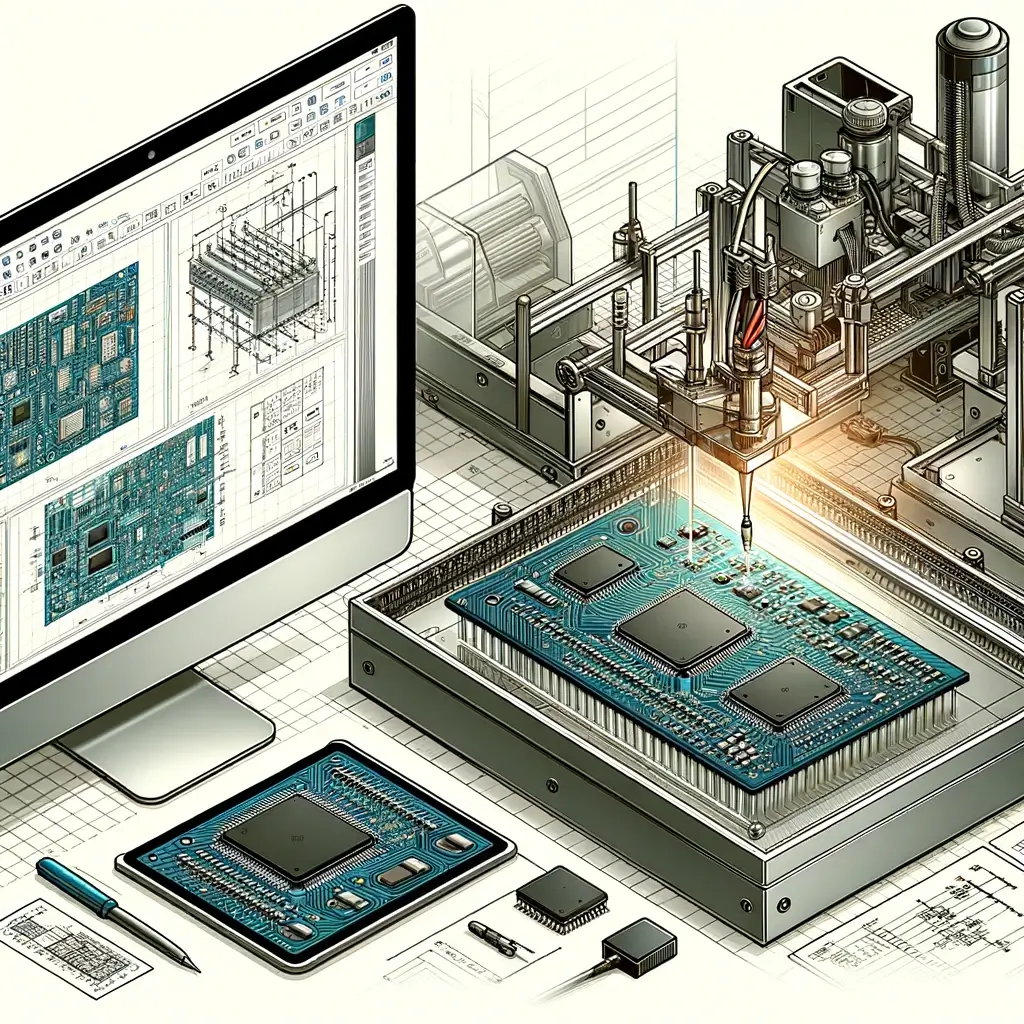
Reflow Soldering—the Process
The basic reflow process consists of four broad steps:
Depositing solder paste on specific pads on a PCB using a predesigned stencil
Placing SMD parts in the paste
Heating the pcb assembly to allow the solder paste to melt (reflow) and wet the PCB pad and the ends of the SMD parts, resulting in the properly soldered connection
Cooling the assembly to the cleaning temperature
Printed Circuit Board
The PCB is the second most crucial ingredient in the reflow process. For proper soldering, it is necessary to bake the boards at elevated temperatures for a certain period, prior to application of solder paste. This drives out the excessive moisture from the board, which may otherwise lead to a large number of defects in soldering.
Some PCBs come with a protective sealer to prevent the exposed surface of copper pads from oxidizing and preventing adherence of solder. The fluxing agent in the solder paste dissolves the sealer as the assembly heats up in the reflow process. Other boards may come with solder-coated pads.
Pad design is critical to proper soldering of SMD components. Designers typically follow one of the international standards specified by IPC, EIA, and others for designing PCBs. This includes the design of different types of vias and the spacing between the pads.