Designers with flexible thinking improve yields and reduce costs.
Rigid-flex pcb is not just another ordinary flexible circuit. A combination of flexible and rigid substrates laminated into a single package presents unique challenges and opportunities. Much of what designers have learned about PCB design comes into question when they start their first rigid-flex PCB. They are no longer designing a two-dimensional substrate but instead, a 3D interconnect that can be bent, folded, and, dare I say, mutilated into a higher performing PCB. Rigid-flex pcb allows designers to replace multilatyer PCBs interconnected with connectors, wires and ribbon cables with a single package offering improved performance and reliability. If the design is confined to a small package, optimize usable space by bending and folding the circuit like an origami swan.
Common Terms
The term “flexible printed circuit board” conjures up images of an alternative to multi-wire ribbon cable. A flat flexible substrate with a single layer of traces connecting one end to the other, such as something most often found connecting the printer head to the control board on an ink jet printer. In flex circuit terms, this constant flexing is known as “dynamic flex.” Flexible circuits used in dynamic flex applications tend to be, but are not limited to, a single layer to achieve the highest yield and greatest reliability. This type of flex circuit best serves interconnecting between sub-systems, like a control board to a print head. A flexible circuit that must be bent and folded at the time of assembly with minimal flexing in its life cycle is known as “flex-to-install.” Flex-to-install construction varies from single to multi-layer based on the application. The limited bending in its life cycle limits the stress on the conductors and facilitates higher layer counts.
When a flex-to-install application requires single-sided component mounting, rigid material can be strategically located and laminated to the flexible circuit to strengthen specific areas. This type of flexible circuit construction is known as “rigidized flex.” The rigid material (typically FR-4) has no conductors and is used primarily to stiffen the substrate in component mounting or connection areas. Rigidized-flex offers an alternative to the high cost of rigid-flex where designers get the benefits of the flexible circuit as well as the strength of rigid material where it is needed. The rigid material does not have to be etched or plated, just drilled and routed, reducing PCB manufacturing processing time.
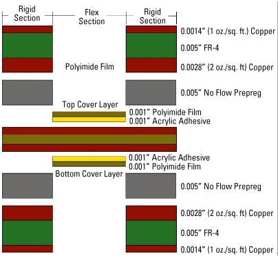
When a flexible application calls for double sided component mounting, or you need an extremely thin PCB, rigid-flex printed circuit board may be the only viable solution. Rigid-flex pcb is a multi-layer PCB with both rigid and flexible layers. A typical four layer rigid-flex PCB starts with a flexible polyimide core with copper foil bonded to both top and bottom sides. The outer rigid layers consisting of single sided FR-4 are laminated to both sides of the flexible core to complete the multi-layer PCB. Rigid-flex pcb has many applications but because of the mixed use of materials and multiple steps in the fabrication process, rigid-flex pcb requires more processing time and higher fabrication costs. To fabricate a multi-layer rigid-flex, the flex layer pairs have to be processed differently from the outer FR-4 layers. The layers of variable materials have to come together at lamination and then be followed by a drilling and plating operation. Thus, a typical four layer rigid-flex PCB, shown in Figure 1, may cost five to seven times more to fabricate than a standard four layer rigid PCB.


