PCB layout plays a core role in the manufacturing of a printed circuit board. The layout process produces a graphical representation of the circuitry that is necessary to manufacture a PCB. PCB design is a detailed description and graphical representation of the circuit. Most of the circuit boards manufactured today are assembled and tested by automated machines, driven in part by the data provided by the PCB files. In this light, the need for PCB layout becomes evident.
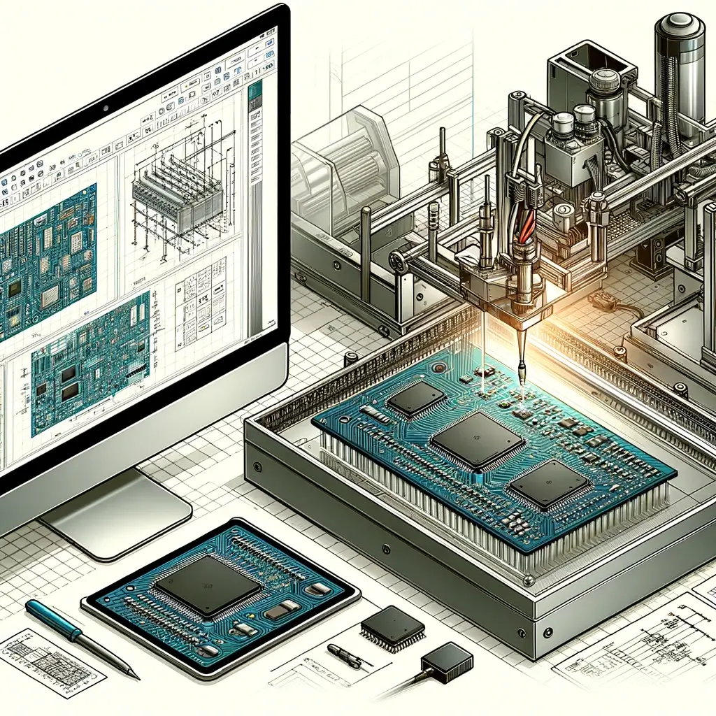
PCB Layout with Computer Aided Design Software, like ORCAD, PADS, Cadence allegro, etc.
With the development of CAD tools by several different companies, it is now common for the PCB layout to be prepared by using CAD software tools. These programs are computer-based applications that offer tools and techniques to effectively and efficiently design a PCB and generate the necessary files to manufacture the board.
Essential Considerations for PCB Design
Design for manufacturability has becoming an increasingly necessary part of the PCB design process. Designers must take into consideration the manufacturing process when designing a board. This requires designers to understand the manufacturing process and how layout affects that process.
The PCB design should consider current flow, size of the circuit, and electromagnetic interference to specify track width. Also, impedance, signal tracks and susceptibility needs to be measured for a particular circuit in order to prepare the precise PCB design. The positioning of components, their alignment and relationship with each other, also has to be thoroughly described in the layout.
Through CAD software, it is possible to prepare a multi-layer design. To maintain visibility, the actual display of different layers is done in separate colors while they are merged into an overlay image.